Arduino In-Circuit Tester: Build Project

Judder

Active member
Feedback
2 (100%)
Credits
976CR
guddler said:
Regarding the cable. Bottom line is there's no real substitute for checking it with a meter.

When I say "beep" below, I mean 470 ohms (and mine reads around 420 Ohms - although the battery light is on in my meter)

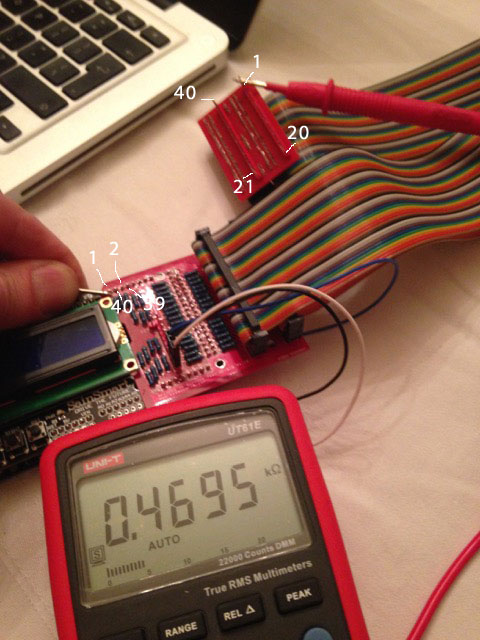
Pin 1 on the CPU should beep out to pin 14 on the Arduino (top left of the shield as the keypad is the correct way up), pin 2, CPU = pin 16, Arduino. Pin 40 of the CPU = pin 15 of the Arduino, pin 39 of the CPU = pin 17 of the Arduino.

Just checking those 4 would be enough to make sure you are correctly orientated.

So I'm back from being away and metered mine out and my second setup of lead orientation is correct

Here's some labelled pictures for everyone else to reference

MeteringArduinoLabelled.jpg


ArduinoTesterMetered2.jpg


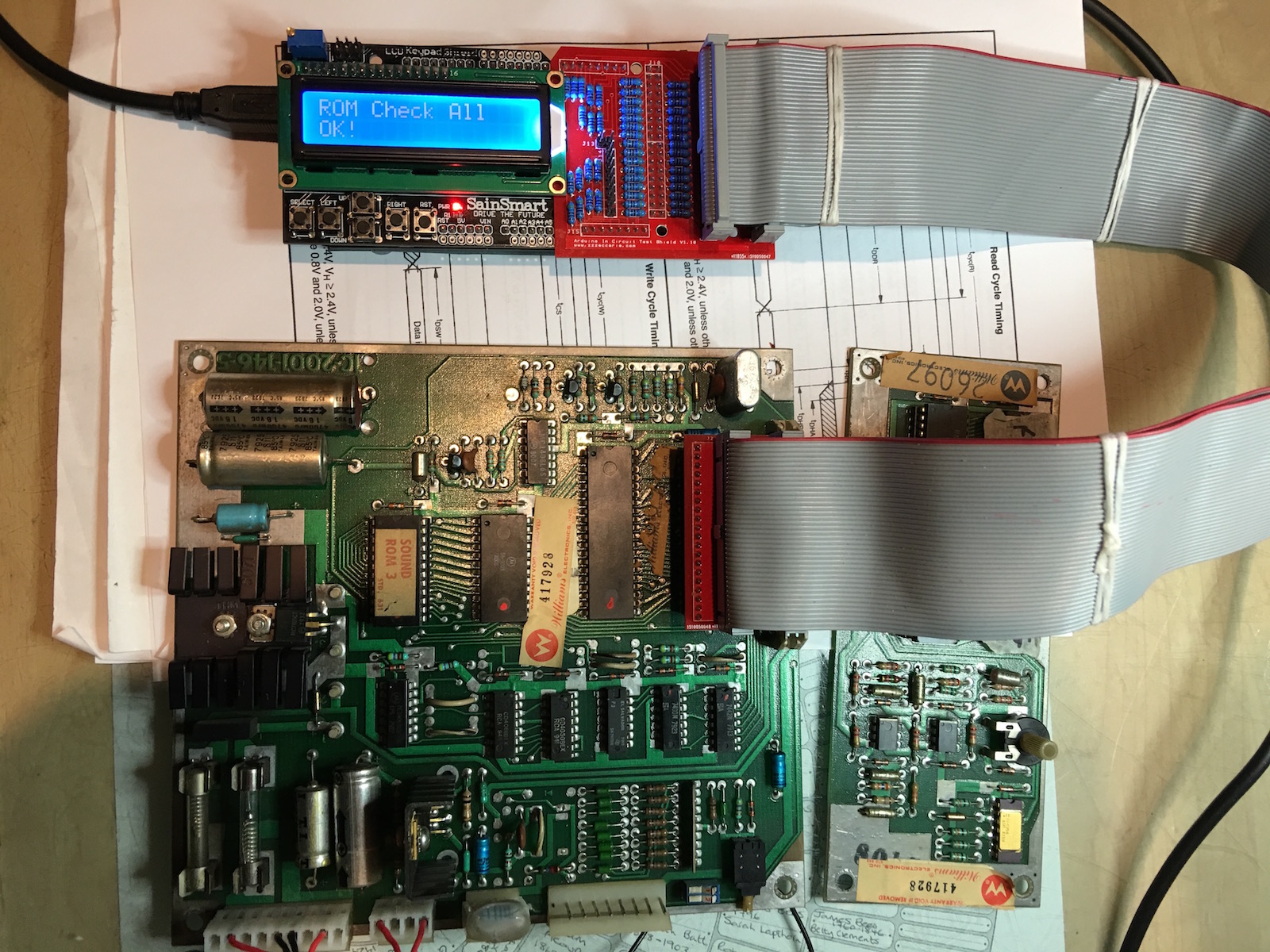
It's not that obvious on the CPU board, but Pin 1 is J2, top-left as you look at the top of the board and has a tiny '*' on the board just by the solder

Paul - maybe on a next revision it might be good to add pin numbers (*or I can add them if I can borrow the source board layout files)?

@Guddler - .4695 kOhms - spot on
smiley2.gif


Alex
 

Dave2084

Active member
vacBacker
Feedback
7 (100%)
Credits
453CR
PaulSwan said:
Point me to your fork/branch and I can take a look.

I now have the RAM Test working.

So onto the next challenge. I/O.

The Williams Sound boards (and lots of 680x stuff) uses the 6821 for I/O.

These need initialising by setting up the Control Register and Data Direction Register in each half, in this case 0x0400/1 and 0x0402/3.

How do I declare these in BaseGame.cpp???

My current attempt doesn't work, as I can't write to them which I'm trying to do in the bus init routine.

Paul, if you have time can you take a look/give me some pointers?

Code here
 

PaulSwan

ZZZ
Feedback
1 (100%)
Credits
1,117CR
You can follow the example for the 8255 in Money Money for adding special setup:

https://github.com/Dave2084/arduino-mega-ict/blob/arduino-mega-ict-6802/libraries/CZ80Cpu/CMoneyMoneyBaseGame.cpp

CMoneyMoneyBaseGame::eek:nBankSwitchSetup8255

I didn't add +5V because it'd need another set of jumpers for each CPU to connect it up and the Arduino didn't seem to be setup to power it this way.

Paul.
 

Dave2084

Active member
vacBacker
Feedback
7 (100%)
Credits
453CR
PaulSwan said:
You can follow the example for the 8255 in Money Money for adding special setup

I've changed my setup code to to use special setup for bank switching but I'm still having no effect, in fact by default the PIA's should be initialised as all inputs but I cant even read them (with the Bank switch code disabled).

Can you take a look at my code to see where I'm going wrong?

As far as I can tell with a logic probe everything is set or pulsing when expected to, so I'm guessing it is a timing issue?
 

PaulSwan

ZZZ
Feedback
1 (100%)
Credits
1,117CR
In general, the cycle is driven by a high pulse on E, so the idle state of E should be low. The idle state of the D bus should be input. The idle state of R_W should be read. No delays should be required, the Arduino is much slower and the 6821 has a max cycle time of 10us.

C6802Cpu::memoryRead

At the start of the read, drive A & R_W. Then, set E high and read in the D. Then set E low to complete the read.

C6802Cpu::memoryWrite

At the start of the write drive A & R_W then set D to output data. Then, set E high and then E low to complete the write cycle. Set the D back to input (hi-z). The set R_W back to read.

The problem you likely have is that you're keeping E high when idle and not low, and not putting R_W back to read causing the writes to be spurious in subsequent cycles. The aim is for the read & writes is to have them start from an idle bus state and leave an idle bus state, ready for the next cycle.

I'm referring to Figure 2 - Bus Timing in the Motorola 6802 datasheet :)
 

Dave2084

Active member
vacBacker
Feedback
7 (100%)
Credits
453CR
Thanks Paul,

Working now!

All that was needed was to move setting E high till after D had been written to. I'm no keeping E low by default as suggested (I was doing that previously but changed things round to try and get it working).

I only added the delays just in case it was happening too fast, but of course they made no difference.

I get a nice pop from the speaker when toggling all the outputs (to the DAC) :D
 

Nes4life

Active member
vacBacker
Feedback
11 (100%)
Credits
1,113CR
I just want to reiterate how awesome this project is and the group effort going into it to improve it further
smiley4.gif


Just waiting on some header pins and my own ICT will be ready. I'm making some headway with the host app for Mac and will have a good portion of the code available in C for other platforms to use. The main idea is for the arduino to hold all the details about the tests it provides for a particular CPU/game and the addresses it can access / read / write. The arduino ICT will continue to work independently but can also pass details to the host app which will then be able to make requests of it from the app's GUI. I'm trying to make a universal protocol so every game / test we support can be extended in this way. Additionally, the app will be able to reprogram the arduino to work with a particular board (selection from a drop-down).

I'll be working with Guddler to prototype the solution and refine it and then I'll pass it by Paul for its suitability as an extension to the existing code. Should make for a nice optional addition anyway.
Nes4life2016-02-03 10:33:47
 

PaulSwan

ZZZ
Feedback
1 (100%)
Credits
1,117CR
Dave, if you feel enthusiastic you can also add something that would generate a tone out of the DAC (by writing out a table of sine wave values in a loop, for example). In the ICT, that'd be writing a "Custom" function. See CGalaxianBaseGame::shellMissileTest for an example of how to add a Custom function.
Paul.
 

Dave2084

Active member
vacBacker
Feedback
7 (100%)
Credits
453CR
PaulSwan said:
Dave, if you feel enthusiastic you can also add something that would generate a tone out of the DAC (by writing out a table of sine wave values in a loop, for example). In the ICT, that'd be writing a "Custom" function. See CGalaxianBaseGame::shellMissileTest for an example of how to add a Custom function.

You must be a mind reader, I've been thinking about that all day!
 

Judder

Active member
Feedback
2 (100%)
Credits
976CR

Dave2084

Active member
vacBacker
Feedback
7 (100%)
Credits
453CR
Thanks for the tips.

I have now code up a basic sound test, it just does 2 different tones each of sinewave, square wave and sawtooth wave ... just 'cos I can. Speed was definitely as issue so I'm down to 24 samples for each sine/sawtooth wave.

It might speed things up if I removed some of the pin checking from read/write but it works just fine.

Also added a load more games and successfully tested ROM checks on a speech board as well.

Code is now on my github fork.

For this little project the last bit is interrupts.

I need to get this to work as the sound inputs drive the PIA CB1 to generate an IRQ to the 6802. This needs testing to ensure it all works properly (the 4068 at IC6 that feeds CB1 is a common fail).
 

guddler

Busting vectors like it's 1982!
vacBacker
Feedback
10 (100%)
Credits
4,048CR
Monday I'll do a PR for Asteroids, I promise
smiley4.gif


The code has been sitting there all done except for adding the sigs for the different variations of ROMs for a while, I've just had real-life things to do instead and will have no time until after the weekend. The good new is that I've got a days holiday on Monday so the plan is, fix the Space Invaders board that is on my bench to clear the last of the stuff for other people and then finish the Asteroids ICT.

"Finish" is such a loose term of course. It just exercises all RAM / ROM / I/O, it could have a bunch more tests in the custom menu but they can be added later and hey, I'm far from the only one that knows Asteroids around here so...
smiley36.gif
 

PaulSwan

ZZZ
Feedback
1 (100%)
Credits
1,117CR
Fixing Space Invaders is a good opportunity to add support for i8080 :)
You'll need to cut the tracks for -5V and +12V on the probe head so they don't connect.
Paul.
 

Dave2084

Active member
vacBacker
Feedback
7 (100%)
Credits
453CR
PaulSwan said:
Fixing Space Invaders is a good opportunity to add support for i8080 :)
You'll need to cut the tracks for -5V and +12V on the probe head so they don't connect.
Paul.

Another reason to get more probe heads ... hows the extra order coming judder?
 

Judder

Active member
Feedback
2 (100%)
Credits
976CR
Dave2084 said:
... hows the extra order coming judder?

Slow pick-up on the re-order thread so I've not placed a second order yet...

However seeing as everyone is speeding along I can get another order through to DirtyPCBs tonight and then we just have to wait for China Post / Hong Kong Post and a good wind for them to turn up

Last time it took circa 2 months, so if we need a speedier result I have 1 (one!) spare here which I had saved for myself for a rainy day, and we can try and ask some of the other guys that I sent out the boards to, to donate theirs until we get a next run in
smiley4.gif


Judder2016-02-04 20:41:54
 
Top