Midway Space Invaders Motherboard

funhouse

Active member
vacBacker
Feedback
3 (100%)
Credits
360CR
Have been trying to get my Midway Space Invaders going today.

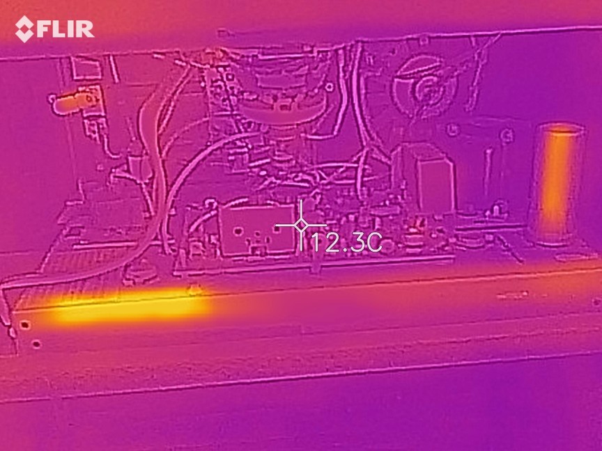
To reduce problems I started with a Jamma switcher with an Arcadeshop Midway adapter on it. The Main Motherboard connector gets the approximate correct 5V, -5V and 12V voltages at the edge connector.

MotherboardFront.jpg


But, as soon as I connect it and switch it on the light on the PSU rapidly fickers and it also ticks quite loudly.

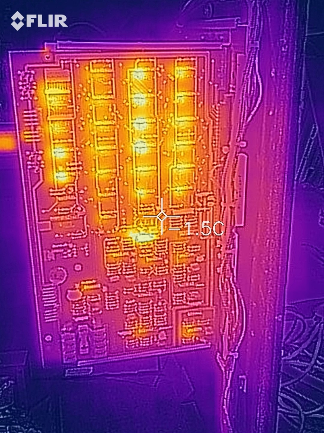
I guess there must be a short somewhere. I removed the daughterboard but the same problem exists so I do think it is something to do with the main motherboard.

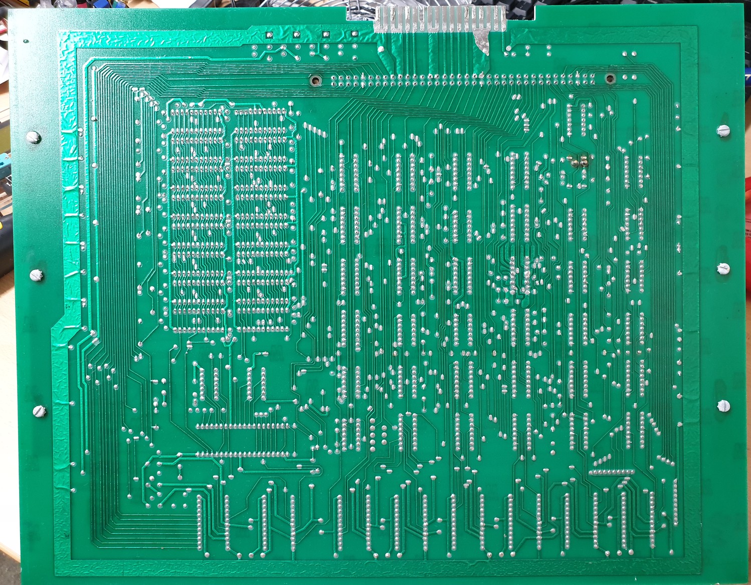
(In the photo above you can see the edge finger connectors are built up with some solder. I did this because the original was worn away on some of the pins. All the fingers are cleaned and isolated as far as I can tell).

Anyone got any suggestions please?

Cheers.
 

Syrup2407

Active member
vacBacker
Feedback
5 (100%)
Credits
163CR
Hi,

Just some thoughts.

If you remove the EPROMS and the microprocessor do you still get the flickering of the PSU?

Can you measure the PSU voltages and let us know the voltages.

I had one board with a shorted tantalum bead capacitor (it was a blue one on the bank of RAM) which pulled down the power supply.

Cheers,

Gav
 

funhouse

Active member
vacBacker
Feedback
3 (100%)
Credits
360CR
Thanks Syrup2407

I removed the socketed EPROMS and the microprocessor but it still does much the same flickering.

The PSU voltages straight out of the connectors are 12.83VDC, -4.81VDC and 5.27VDC

I measured the resistance of the blue and green small capacitors around the RAM and they all were 2 Ohms or above.
 

Lurch666

Active member
Feedback
21 (100%)
Credits
4,142CR
Can you show your connections to the motherboard?

Thinking maybe you might have a wire wrong going to the motherboard.

Also does the supply exhibit the same behaviour when it's not connected to the pcb?
 

funhouse

Active member
vacBacker
Feedback
3 (100%)
Credits
360CR
Hi, the problem only occurs when I connect the edge connector.

I'm pretty sure the wiring is correct but I will take another look and photo it.
 

philmurr

Active member
vacBacker
Feedback
46 (100%)
Credits
2,302CR
What do you get if you measure the resistance across 5V & 0V, and between 12V & 0V on the game board?

If you have access to a linear PSU, **and are prepared to take the risk**, try connecting it up to blow the faulty component.
 

funhouse

Active member
vacBacker
Feedback
3 (100%)
Credits
360CR
philmurr said:
What do you get if you measure the resistance across 5V & 0V, and between 12V & 0V on the game board?

Thanks Phil. Can I measure that across the appropriate pins with power disconnected do you think?

I have a linear Power supply that was working but I had assumed that it was now broken - perhaps not and it was this problem that I was seeing.

I'll gladly blow some parts up in the name of progress!!

funhouse2019-05-04 17:32:40
 

funhouse

Active member
vacBacker
Feedback
3 (100%)
Credits
360CR
Here's the edge connector:

18pinEdge.jpg


From bottom pin 1 is 5VDC, pin 3 is 12VDC and pin 5 is -5V DC or thereabouts and I think that is correct.
 

funhouse

Active member
vacBacker
Feedback
3 (100%)
Credits
360CR
Well many thanks for that idea Phil - it's an obvious test that completely evaded me!!

Infinite resistance between 5V and 0 and also between -5V and zero.

BUT! only 3 Ohms slowly decaying to 0.7 Ohms between 0 and 12V.

Getting closer ..............
 

Lurch666

Active member
Feedback
21 (100%)
Credits
4,142CR
Connector looks good and obviously the fault is on the board.

It's just the amount of times I've messed up the wiring on a connector.

Have you checked the underside of the board to see if any component lead has bent and is touching something it shouldn't?

Sometimes on these boards there can be quite a long bit of a component leg sticking out on the solder side.
 

funhouse

Active member
vacBacker
Feedback
3 (100%)
Credits
360CR
I don't think this cab has ever been modified so I assume that the wiring is all okay, or at least in the right place.

I have spent some time looking for shorts on both sides of the board. At one stage I thought one of the brown capacitors had bent down and was touching an IC leg - but I bent it back and no difference. I also found a small piece of old solder that was bridging two pins on the daughterboard but that still isn't this problem.

Here is a photo of the underside. (I found that if you right-click it and copy-image it is the full version which can be pasted and zoomed on an image viewer and it is easier to see. Also you can right-click images and choose 'open image in new tab' and they are bigger).

Anyway here is the underside:

MotherboardRear.jpg


funhouse2019-05-04 18:25:30
 

RaveN

Active member
vacBacker
Feedback
1 (100%)
Credits
1,325CR
One of my boards measures about 2K ohm between 0->12v

Take one action at a time and keep measuring.

1- Roms okay, 9316 and don't use 12v.
2- Remove CPU, re-test.
3- Capacitors - Snip one side one at a time and re-measure (assuming you have access to a soldering iron to put them back in place).
- 10uF elec cap, 3 next to each other, the one closest to the RAM and furthest from the daughter card slot.
- Green Tantalum next to the CPU socket.
- Blue Tantalum cap inbetween the 2 rows of RAM, at the top towards the CPU. These often fail. Later boards were fitted with more reliable film capacitors.

Failing that, and you're sure there's no trace shorts, then do what Philmurr suggests and apply voltages and see what gets hot.
 

funhouse

Active member
vacBacker
Feedback
3 (100%)
Credits
360CR
Thanks all.

I've gone through the list and got to the blue tantalum between the ram. Taking it out and reading on a capacitance meter says it's leaky and it has 0 resistance. I replace it with what I have from a donor board (I am hoping it is the correct type and good enough to temporarily substitute as it's 15.8uF at 35V versus the blue which says 22 at 25V):

TantalumCapComparison.jpg


I check the resistance now and it reads infinite like the other voltages. Great I think.

I put it back in the cab and power on but the PSU ticks again. I take the board out and measure across 0 to 12V again and once again it's only a few Ohms. I take out the donor capacitor to test and it is dead. I think something on the board is killing these.

Does that give me any clues?

Cheers.

funhouse2019-05-05 16:40:57
 

funhouse

Active member
vacBacker
Feedback
3 (100%)
Credits
360CR
Syrup2407 said:
Do you have access to an oscilloscope which you can use to see if there are any spikes on the 12V?

I do have an oscilloscope but I have to admit that I am a major amateur in using it!

Am about to try running the board without the capacitor first.

Cheers.
 

funhouse

Active member
vacBacker
Feedback
3 (100%)
Credits
360CR
Just tried without that tantalum. On its own without ROMS and processor it powered up fine - no noise. Same with ROMS and processor. With the daughterboard the same too.

No game sounds or picture though - I played with the coin mech. to add credits to no avail.

Here are some heat photos:

Main board:

main_heat.jpg


Daughter board:

daughter_heat.jpg


CRT chassis etc.

monitor_heat.jpg


funhouse2019-05-05 20:42:03
 

funhouse

Active member
vacBacker
Feedback
3 (100%)
Credits
360CR
Yes, you are right - the bottom left one on the photo next to where the tantalum is looks much hotter doesn't it.

Will have another go tomorrow with the screen. I do fear that it needs work though as I remember switching it on a year or so ago and hearing a fizzing noise from the chassis.

Edit. Anyone know where I can source the RAM from?

Cheers.

funhouse2019-05-05 22:01:17
 
Top