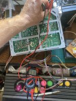
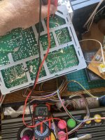
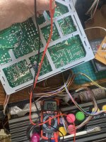
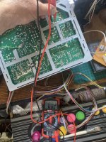
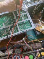
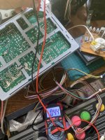
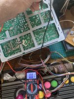
Pentranic chassis screen jumps

Martinmurphy30

User
vacBacker
Feedback
4 (100%)
Credits
409CR
If this is a working monitor/chassis arrangement which by all accounts is completely different to what the original post/issue/ actual monitor chassis problem was.....ie, the screen jumps due to a voltage increase when the screen blanks, on a chassis where the IC supply is derived from the flyback.....why don't you scope the power supply to the ic when the screen blanks to actually see if the voltage spikes? Before you ruin a working setup on a fix for a different setup?
 

Retroman839

Senior Member
vacBacker
Feedback
12 (100%)
Credits
7,252CR
If this is a working monitor/chassis arrangement which by all accounts is completely different to what the original post/issue/ actual monitor chassis problem was.....ie, the screen jumps due to a voltage increase when the screen blanks, on a chassis where the IC supply is derived from the flyback.....why don't you scope the power supply to the ic when the screen blanks to actually see if the voltage spikes? Before you ruin a working setup on a fix for a different setup?
Not sure I get your question totally …

I could scope it but this is a known issue with this chasiss and the original designer created a work around for the issue .

I am following that work around.

I have watched the monitor
On lots of diffrent jamma set ups and the white outs cause the screen to jump.

it’s a known issue with this chasis ..why would I not follow the work around ?


Couple caps
A resister change
A diode to fit
And a jumper wire
 
Last edited:

Martinmurphy30

User
vacBacker
Feedback
4 (100%)
Credits
409CR
Do you have a scope? Connect the scope to the IC supply and ground, set it to record and blank the monitor, did the voltage reading increase? If yes this fix MAY be relevant, if no your wasting your time...you need to find the issue before you can fix it
 

Retroman839

Senior Member
vacBacker
Feedback
12 (100%)
Credits
7,252CR
Do you have a scope? Connect the scope to the IC supply and ground, set it to record and blank the monitor, did the voltage reading increase? If yes this fix MAY be relevant, if no your wasting your time...you need to find the issue before you can fix it
I do have a scope
I can still do that.

I have completed the work around already and I’m not removing it and putting back as it was .. just going with it .. I have good faith that the discription of the known fault matches my issue .
 

Martinmurphy30

User
vacBacker
Feedback
4 (100%)
Credits
409CR
Is the issue not that your monitor chassis does not match the original fix though? You don't have the components listed in the fix, yes you have spaces for them but what are you actually changing? If the components were not populated in the first place how is this fix relevant? Where is the IC supply coming from If the diode, resistor and capacitor are not even in your chassis from factory?!
 

Retroman839

Senior Member
vacBacker
Feedback
12 (100%)
Credits
7,252CR
Is the issue not that your monitor chassis does not match the original fix though? You don't have the components listed in the fix, yes you have spaces for them but what are you actually changing? If the components were not populated in the first place how is this fix relevant? Where is the IC supply coming from If the diode, resistor and capacitor are not even in your chassis from factory?!
Swapped a resister .

Fitted a missing cap

Same place all empty holes are connected underneath with solder.

Componamts absent -
Bridged with solder.

Lifting the new resister leg out of circuit then bridged to diode offers a more stable / controlled flow . As intended ..
but not realised at manafacture for reasons unknown ( didnt have the parts at the time ?)


Also this chassis isn’t usable as is …
Every game uses flashes for impact all the
Time . It’s unplayable the
Way the screen jumps ..
Só I wouldn’t describe this chasiss good working, its faulty.
 
Last edited:

Martinmurphy30

User
vacBacker
Feedback
4 (100%)
Credits
409CR
You didn't have a diode to begin with, this is my point, your chassis is DIFFERENT, measure the voltage at the IC on a blank. Is the IC supply on your chassis even derived from the flyback?
 

Retroman839

Senior Member
vacBacker
Feedback
12 (100%)
Credits
7,252CR
You didn't have a diode to begin with, this is my point, your chassis is DIFFERENT, measure the voltage at the IC on a blank. Is the IC supply on your chassis even derived from the flyback?
I did ask that
Question already in this thread ..

As long as the
Resister is lifted its out of that circuit what ever circuit thet was that was supplyimg
It ..

If I get no voltage now then I can investigate that aveue at
That juncture ..

To proceed with the work around from Rick neiman seems like the correct path to me .. which I have done ..
Now is to test voltages ?
No ?
I mean we are where we are are we not ?

Let’s test

I would say
That if flyback is workimg
Hard to produce white bright screen .. these residual volts that cause a slight over
Voltage to the vcc of the horizontal output means I am connected to the flyback.
 
Last edited:

Martinmurphy30

User
vacBacker
Feedback
4 (100%)
Credits
409CR
So your saying pentatonic couldn't afford a couple of components, so rick the almighty decided he would come up with a fix for it...and even though your chassis is different, this is the fix. Good luck, I've tried explaining it to you, I'm done.
 

Retroman839

Senior Member
vacBacker
Feedback
12 (100%)
Credits
7,252CR
So your saying pentatonic couldn't afford a couple of components, so rick the almighty decided he would come up with a fix for it...and even though your chassis is different, this is the fix. Good luck, I've tried explaining it to
So your saying pentatonic couldn't afford a couple of components, so rick the almighty decided he would come up with a fix for it...and even though your chassis is different, this is the fix. Good luck, I've tried explaining it to you, I'm done.
Appreciate everything you
Have said .. thank you for your advice. I will try to hook my scope onto the
Vcc.. If I get this thing to live
.
I will ask him .

On a side note ..
My mate worked building chasiss for a tv company .
“ if we
Don’t have that part just bridge it to the
Next part”

Thats what hé was told
To do. Maybe thsts
Was just caps though.
 

gunblade

Active member
vacBacker
Feedback
22 (100%)
Credits
8,735CR
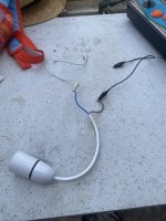
desolder and isolate the collector pin of the HOT from the chassis, connect one side of lamp to flyback collector pin and the other side to common/ground
read b+ and then read 25v, but you won;t get anything on 25v unless you connected the anode of the diode to pin 3 of the transformer

Why the manufacturer of this chassis did not run all the ic supply from the 25v line is a mystery to me
 

Retroman839

Senior Member
vacBacker
Feedback
12 (100%)
Credits
7,252CR
Yep it’s odd
desolder and isolate the collector pin of the HOT from the chassis, connect one side of lamp to flyback collector pin and the other side to common/ground
read b+ and then read 25v, but you won;t get anything on 25v unless you connected the anode of the diode to pin 3 of the transformer

Why the manufacturer of this chassis did not run all the ic supply from the 25v line is a mystery to me
desolder and isolate the collector pin of the HOT from the chassis, connect one side of lamp to flyback collector pin and the other side to common/ground
read b+ and then read 25v, but you won;t get anything on 25v unless you connected the anode of the diode to pin 3 of the transformer

Why the manufacturer of this chassis did not run all the ic supply from the 25v line is a mystery to me
I can ask Rick
 
Top