You are using an out of date browser. It may not display this or other websites correctly.
You should upgrade or use an alternative browser.
You should upgrade or use an alternative browser.
Pentranic chassis screen jumps
- Thread starter Retroman839
- Start date
i tried continuity mode from anode in suction cup across thst circuit and no continuityso if you look at the location of d506 it looks like sweet fa goes to the anode, is that correct?

The anode side of the diode, NOT the eht! 🤣😂
I thought that was the cathode ?The anode side of the diode, NOT the eht! 🤣😂

Seems I’m missing r126 & r500 ?
One side is the anode, the opposite side is the cathode. Which in the schematic posted is connected directly to pin 3 of t501, which is why grant asked if your chassis has anything connected in-between.
Thanks.One side is the anode, the opposite side is the cathode. Which in the schematic posted is connected directly to pin 3 of t501, which is why grant asked if your chassis has anything connected in-between.
Só looks like r500 is between ?
Yep i can see sweet fa on the schimatic between d506 and pin 3.
It’s been a long day 😊
I will assume then that the r500 is supposed to be unoccupied
It’s been a long day 😊
I will assume then that the r500 is supposed to be unoccupied
Yep i can see sweet fa on the schimatic between d506 and pin
ignore r500
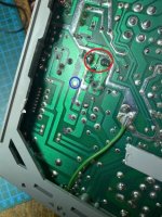
on this picture is the red circle C313?
the blue circle i believe will be the where the anode of d506 needs to go via a wire link

This is the cap
I cannot see 313 but I will scrap that gunk off next to it.
This is a new cap replaced the other like for like ..

Rick neiman said connect to r318 ( swapped for a 680 ohm )To me it looks like this. So you connect a wire from the pad in the yellow circle to the anode of D506 (or to the resistor R500 connected to the anode).
View attachment 57347
Iv looked all over cannot seeignore r500
on this picture is the red circle C313?
the blue circle i believe will be the where the anode of d506 needs to go via a wire link
C313
As I cannot see ident for this cap .. good chance it is c313
Can I continuity the posative leg of this cap to d501

D501 has continuity to that cap posative leg 👍
Só yeh it’s cap 313
Last edited:
mkl is saying what i am saying
install d506 and c333
put a wire on the pad marked by the yellow circle in mkl's pic, the other end of that wire goes to a free pad of the anode of d506, using a free pad of the cathode d506 run a wire to the your new resistor r318
personally I would do all the above but leave the connection onto r318 off, dummy load the collector of the HOT and of course isolate the pin of the HOT from the circuit and then read the voltage at the cathode of d506 - just to make sure you are getting 24v or close
Ok I got it
Don’t I leave a leg of d506 up and solder wire to it ?
Or do I have free pads ?
Not aware of free pads of 506 hete is a pic of solder side of d506
Jumps across them 3 traces.
Any pad of the 3 bottom pads is good then for the jumper wire ?
Don’t I leave a leg of d506 up and solder wire to it ?
Or do I have free pads ?
Not aware of free pads of 506 hete is a pic of solder side of d506
Jumps across them 3 traces.
Any pad of the 3 bottom pads is good then for the jumper wire ?
Last edited:
Thats 2 wires then in total
Yellow circle to anode of
D506
Cathode Side of d506 to my new resistor .
Ok then…. Simples 😬
Nah I got it 😊👍
Thanks a heap
And I should have the d506
Hopefully this weekend if not early week
I would love to do the dummy load if you can guide me on that also …
🙏
Yellow circle to anode of
D506
Cathode Side of d506 to my new resistor .
Ok then…. Simples 😬
Nah I got it 😊👍
Thanks a heap
And I should have the d506
Hopefully this weekend if not early week
I would love to do the dummy load if you can guide me on that also …
🙏
Last edited:
use the pads that are free, it looks neater
install the diode and cap first then add the two wire links that need doing and use free pads/through holes
obviously the wire link from the transformer will need to solder side of the chassis but the other link can go component side
install the diode and cap first then add the two wire links that need doing and use free pads/through holes
obviously the wire link from the transformer will need to solder side of the chassis but the other link can go component side
Got it ..use the pads that are free, it looks neater
install the diode and cap first then add the two wire links that need doing and use free pads/through holes
obviously the wire link from the transformer will need to solder side of the chassis but the other link can go component side
Jumper wire just pops through the through hole making it a neat job ..
Rather than have componants legs flying all over shop with wires solderd to them ..
R318 don’t have a free pad though ..
But d506 looks to have some