You are using an out of date browser. It may not display this or other websites correctly.
You should upgrade or use an alternative browser.
You should upgrade or use an alternative browser.
Arduino In-Circuit Tester: Build Project
- Thread starter Judder
- Start date

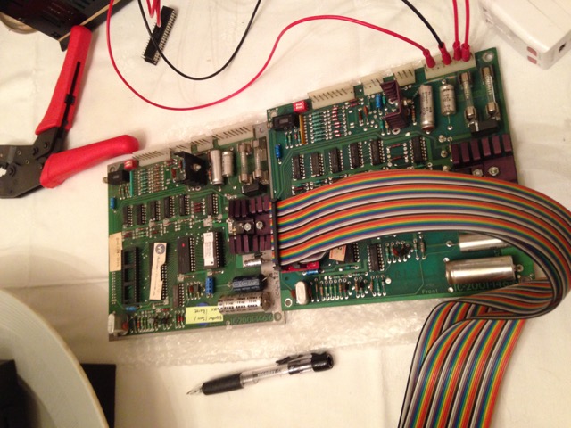
So I've been working on the Defender CPU/ROM/Interface board code again over the weekend.
I now have it working to the point I can test:
All the ROM (red only for now)
CMOS RAM
Inputs
Outputs
What I still need to do:
Interrupts generated by the ROM board PIA (Interface PIA Interrupts are not used)
DRAM
Custom routines as required (to start off one to cycle trough the sound outputs like the in game test does)
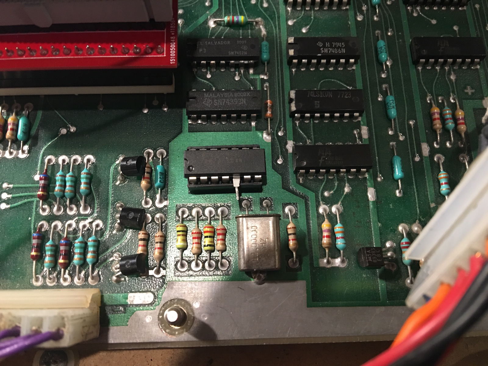
As I suspected the DRAM doesn't work out of the box.
I'm using an early series CPU here s to use the clock mastering I socketed 3B and the clock input goes to pin 5:
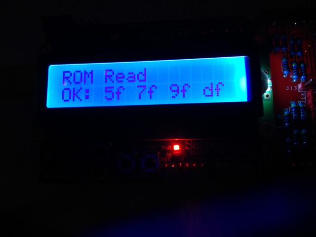
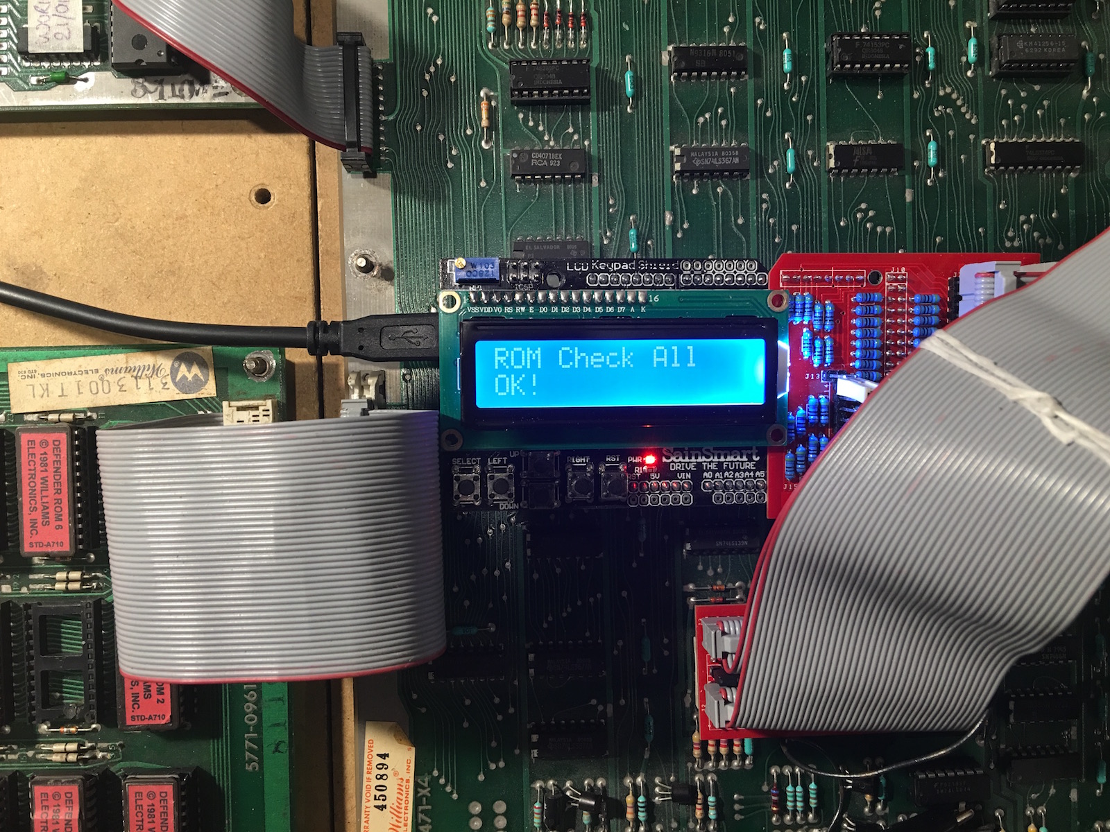
ROM Test results:
I now have it working to the point I can test:
All the ROM (red only for now)
CMOS RAM
Inputs
Outputs
What I still need to do:
Interrupts generated by the ROM board PIA (Interface PIA Interrupts are not used)
DRAM
Custom routines as required (to start off one to cycle trough the sound outputs like the in game test does)
As I suspected the DRAM doesn't work out of the box.
I'm using an early series CPU here s to use the clock mastering I socketed 3B and the clock input goes to pin 5:
ROM Test results:
This thread is really awesome! I remember running across Paul Swan's ICT boards a while back, but never really pursued it. Now that I see all this work using it, it is very exciting. I joined this forum explicitly because of this thread (but been on KLOV for a few years now). I now have an Arduino kit on the way, PCBs at the fab and hoping to build them up towards the end of this month.
I'm currently piecing a Bubbles back together, and also have a sickly Defender (that's currently running a JROK, but I'd like to get the original hardware running) so all this work on the Williams boards will come in handy. I'm hoping I'll be able to contribute as well once I get my setup together. This platform seems extremely versatile, even if it might not completely replace a Fluke, at least it will do 90% of it for 10% of the price tag.")
Dave, I reference your site often when identifying Williams boards and working through all the differences, so thanks for providing that, as it's such an asset to the community.
I'm currently piecing a Bubbles back together, and also have a sickly Defender (that's currently running a JROK, but I'd like to get the original hardware running) so all this work on the Williams boards will come in handy. I'm hoping I'll be able to contribute as well once I get my setup together. This platform seems extremely versatile, even if it might not completely replace a Fluke, at least it will do 90% of it for 10% of the price tag.
Dave, I reference your site often when identifying Williams boards and working through all the differences, so thanks for providing that, as it's such an asset to the community.
neutrino said:I'm currently piecing a Bubbles back together
Once I have the code in slightly better shame and can test everything but the DRAM I'll add the later 1st generation games (Stargate, Robotron, Sinistar, Joust Bubbles and Splat!). The memory map and bank switching is completely different but will be easy enough to redo my Defender drivers.
neutrino said:even if it might not completely replace a Fluke, at least it will do 90% of it for 10% of the price tag.
More like 1%, have you seen how much a 6809 Pod goes for these days? (and you'd still need a 9010A or 9100!)
Dave2084 said:Once I have the code in slightly better shame and can test everything but the DRAM I'll add the later 1st generation games (Stargate, Robotron, Sinistar, Joust Bubbles and Splat!). The memory map and bank switching is completely different but will be easy enough to redo my Defender drivers.
That sounds great. You've definitely been very busy and it sounds like you're making good progress on this. Much appreciated effort.
Dave2084 said:More like 1%, have you seen how much a 6809 Pod goes for these days? (and you'd still need a 9010A or 9100!)
Ha ha ha, yes very true! I paused a moment when I wrote the original number thinking I was still be generous with that figure. That is why I don't currently have any Fluke equipment...it's just too expensive and I can't justify spending what they are going for right now, assuming you can even snap one up before everyone else looking for one.
neutrino2016-02-14 18:30:07
I've been really enjoying reading this thread.
As someone who has worked on various software projects, I know how frustrating it is when you've poured in loads of effort and someone pops up and says "now you have done x please do y".
But yes I'm going to be that guy and ask how complex it will be to add cpus like the z80 and eventually something like the 68k?
dj_yt said:But yes I'm going to be that guy and ask how complex it will be to add cpus like the z80 and eventually something like the 68k?
Z80 is already supported for a limited number of games. I'm very interested in seeing this developed more as it is the only one of the frequently used CPUs that I don't have a fluke pod for.
68k might be tricky as the Arduino probably doesn't have enough pins, not looked at it though.
Hey Dave
Here some feedback on the soundboard testing code (and two sets of test results below)
Bus Idle, ROM Read All, RAM Write All AD, RAM Write All Lo, RAM Write All Hi, RAM Read All
All of these return OK even if the tester isn't correctly connected.
The most useful (from testing) are RAM Write-Read and ROM Check as these give definitive signature results
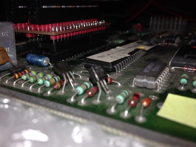
I originally had mine not connected properly as the pins on the test 'POD' are a bit too big for the CPU socket, so was getting false positives
To make things fit together, I fitted pin sockets (the 'turned' ones don't fit so I used the spring type ones) to the bottom of the test 'POD' so that the pins going into the Williams ROM socket are much thinner = successful results
@Paul - not sure what we can do about that with the use of the jumpering pins, but they are a bit too big for easy slot in / slot all different boards
Results of a Stargate and a Joust sound board - which I'm guessing is showing that the Stargate ROM is incorrect and needs to be replaced, but the RAM is good
548112
Bus Idle = OK
Bus Check = OK
ROM Check All = E:U12 f801 04 1b
RAM Check All = OK
RAM Check All CS = OK
Interrupt Check =
Input Read U10 ff Pb0-7 = OK: 7f
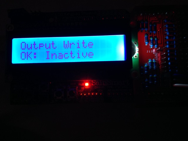
Output Write U10 ff PA0-7 = OK: Inactive / Active (flip flop)
ROM Check f800 ff U12 = E:U12 f840 04 1b
ROM Read f800 ff U12 = OK: df 0f 8e 00
RAM Check 0000 ff U11 = OK
RAM Write-Read 0000 ff U11 = OK: 11 22 44 88
ROM Read All = OK!
RAM Write All AD = OK!
RAM Write All Lo = OK!
RAM Write All Hi = OK!
RAM Read All = OK!
Custom Test DAC = DAC Tested!
D-8224-3006
Bus Idle = OK
Bus Check = OK
ROM Check All = OK
RAM Check All = OK
RAM Check All CS = OK
Input Read = OK: 3f
ROM Check f000 ff U12 = OK
ROM Read f000 ff U12 = OK: 74 0f 8e 00
RAM Check 0000 ff U11 = OK
RAM Write-Read 0000 ff U11 = OK: 11 22 44 88
ROM Read All = OK
RAM Write All AD = OK
RAM Write All Lo = OK
RAM Write All Hi = OK
RAM Read All = OK
Judder2016-02-16 10:18:55
Here some feedback on the soundboard testing code (and two sets of test results below)
Bus Idle, ROM Read All, RAM Write All AD, RAM Write All Lo, RAM Write All Hi, RAM Read All
All of these return OK even if the tester isn't correctly connected.
The most useful (from testing) are RAM Write-Read and ROM Check as these give definitive signature results
I originally had mine not connected properly as the pins on the test 'POD' are a bit too big for the CPU socket, so was getting false positives
To make things fit together, I fitted pin sockets (the 'turned' ones don't fit so I used the spring type ones) to the bottom of the test 'POD' so that the pins going into the Williams ROM socket are much thinner = successful results
@Paul - not sure what we can do about that with the use of the jumpering pins, but they are a bit too big for easy slot in / slot all different boards
Results of a Stargate and a Joust sound board - which I'm guessing is showing that the Stargate ROM is incorrect and needs to be replaced, but the RAM is good
548112
Bus Idle = OK
Bus Check = OK
ROM Check All = E:U12 f801 04 1b
RAM Check All = OK
RAM Check All CS = OK
Interrupt Check =
Input Read U10 ff Pb0-7 = OK: 7f
Output Write U10 ff PA0-7 = OK: Inactive / Active (flip flop)
ROM Check f800 ff U12 = E:U12 f840 04 1b
ROM Read f800 ff U12 = OK: df 0f 8e 00
RAM Check 0000 ff U11 = OK
RAM Write-Read 0000 ff U11 = OK: 11 22 44 88
ROM Read All = OK!
RAM Write All AD = OK!
RAM Write All Lo = OK!
RAM Write All Hi = OK!
RAM Read All = OK!
Custom Test DAC = DAC Tested!
D-8224-3006
Bus Idle = OK
Bus Check = OK
ROM Check All = OK
RAM Check All = OK
RAM Check All CS = OK
Input Read = OK: 3f
ROM Check f000 ff U12 = OK
ROM Read f000 ff U12 = OK: 74 0f 8e 00
RAM Check 0000 ff U11 = OK
RAM Write-Read 0000 ff U11 = OK: 11 22 44 88
ROM Read All = OK
RAM Write All AD = OK
RAM Write All Lo = OK
RAM Write All Hi = OK
RAM Read All = OK
Judder2016-02-16 10:18:55
One addition on the best way to adapt the jumper pins the POD is using to the CPU sockets of the motherboards being tested
I found that if you use a standard 'sprung' socket to connect to the legs on the jumper pins, these fits nice and tightly as the sprung socket can adapt to the wider size of the jumper pins
However the legs of the 'sprung' sockets are very weak as they are meant to be soldered to the boards, so I used a 'turned' socket next in line to provide stronger mounts - here's a quick picture
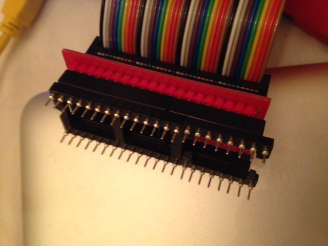
Works very nicely and reliably...
I found that if you use a standard 'sprung' socket to connect to the legs on the jumper pins, these fits nice and tightly as the sprung socket can adapt to the wider size of the jumper pins
However the legs of the 'sprung' sockets are very weak as they are meant to be soldered to the boards, so I used a 'turned' socket next in line to provide stronger mounts - here's a quick picture
Works very nicely and reliably...
Judder said:One addition on the best way to adapt the jumper pins the POD is using to the CPU sockets of the motherboards being tested
I found that if you use a standard 'sprung' socket to connect to the legs on the jumper pins, these fits nice and tightly as the sprung socket can adapt to the wider size of the jumper pins
However the legs of the 'sprung' sockets are very weak as they are meant to be soldered to the boards, so I used a 'turned' socket next in line to provide stronger mounts - here's a quick picture
Works very nicely and reliably...
I didn't use the square pins on my CPU connectors, instead I use turned pin headers. Still using a sacrificial socket though.
Judder said:Hey Dave
Here some feedback on the soundboard testing code (and two sets of test results below)
Bus Idle, ROM Read All, RAM Write All AD, RAM Write All Lo, RAM Write All Hi, RAM Read All
All of these return OK even if the tester isn't correctly connected.
I did add check for power and busses to the memory tests, but commented them out to improve performance. I'll take a look.
Judder said:Results of a Stargate and a Joust sound board - which I'm guessing is showing that the Stargate ROM is incorrect and needs to be replaced, but the RAM is good.
ROM Check f800 ff U12 = E:U12 f840 04 1b
Sort of ... the test is telling you that 0xf840 is 0x1b and should be 0x04.
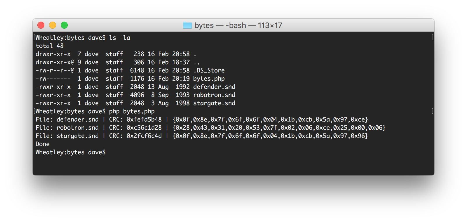
In fact if you look at location 0x40 of the Stargate sound ROM you'll see that it is actually 0x1b. The reason? A typo in the constant set up for expected values. In the beginning I was typing these in manually and here's the result.
I have since written a PHP script to do it for me automatically on the command line of my Macbook as once you get to full games there are too many ROMs to do it like this.
To fix it for Stargate you need to change line 46 of CWilliamsSoundGame.php from:
static const UINT8 s_romData2nSet2_IC12[] = {0x0f,0x8e,0x7f,0x6f,0x6f,0x04,0x04,0x1b,0x5a,0x97,0x96};
to:
static const UINT8 s_romData2nSet2_IC12[] = {0x0f,0x8e,0x7f,0x6f,0x6f,0x04,0x1b,0xcb,0x5a,0x97,0x96};
as you can see I got 40 and 80 wrong here!
I'll run the script on all the sound ROMs and push the change to github tonight.
Dave20842016-02-16 12:50:05
Dave2084 said:In fact if you look at location 0x40 of the Stargate sound ROM you'll see that it is actually 0x1b. The reason? A typo in the constant set up for expected values. In the beginning I was typing these in manually and here's the result....
I'll run the script on all the sound ROMs and push the change to github tonight.
Great Dave - shows how a group of us writing and testing this can make lighter work of getting it all 100%
I'll run Defender and Robotron tonight and check that those go through too, though the auto-generated arrays will make light work of getting these correct as you say

Judder2016-02-16 13:59:00
Dave2084 said:I did add check for power and busses to the memory tests, but commented them out to improve performance. I'll take a look.
A basic VCC +5 (pin 8) & VSS GND (1 & 21) test would be good, just to verify connectivity
Also is there anyway to test the clock signal coming in through EXTAL (39) - might be interesting to verify the crystal is working as quite a few board I've seen have this dented / broken / hanging off
Also, a strange one, but my natural reaction with the buttons on the SainSmart screen is to use the 'RESET' button on the right as the 'run test' button, rather than the 'SELECT' one on the far left set correctly / logically at the moment
I know we'd be breaking protocol of the labels for the buttons if we swapped them but I might try it locally and see if it 'feels' easier to use - I think it probably will...
Been out of the country for a week, back now.
Re: GND/Vcc check should be/is part of the Bus Check ("check" function). It's the first thing everyone should do after setting up. No need to do it on every cycle.
Re: DRAM. 4116 is arranged as a 128x128 matrix. To keep it refreshed needs a RAS on each row every 2ms. Therefore, if you setup the RAM region to be just 128 bytes in size, it should always hit the same row and thus has the best chance of passing RAM Test. If this works for one row, we can look at modifying the RAM Test to run in column+row order instead of natural row+column order so that every cycle refreshes a row.
Re: xtal - it's easy to see if that's working with a real CPU + scope.
Re: PHP for generating the ROM descriptions - can you add a utilities folder and check it in along with notes on how to use it?
Whilst away I've been adding support for 6502 in clock master form for Astro Fighter. Coded up but not tested on real hardware yet.
https://github.com/prswan/arduino-mega-ict/tree/6502_clock_master
It includes some bug fixes in the standard 6502 implementation as well that would be good to verify work OK with Asteroids...
Paul.
Re: GND/Vcc check should be/is part of the Bus Check ("check" function). It's the first thing everyone should do after setting up
. No need to do it on every cycle.Re: DRAM. 4116 is arranged as a 128x128 matrix. To keep it refreshed needs a RAS on each row every 2ms. Therefore, if you setup the RAM region to be just 128 bytes in size, it should always hit the same row and thus has the best chance of passing RAM Test. If this works for one row, we can look at modifying the RAM Test to run in column+row order instead of natural row+column order so that every cycle refreshes a row.
Re: xtal - it's easy to see if that's working with a real CPU + scope.
Re: PHP for generating the ROM descriptions - can you add a utilities folder and check it in along with notes on how to use it?
Whilst away I've been adding support for 6502 in clock master form for Astro Fighter. Coded up but not tested on real hardware yet.
https://github.com/prswan/arduino-mega-ict/tree/6502_clock_master
It includes some bug fixes in the standard 6502 implementation as well that would be good to verify work OK with Asteroids...
Paul.
I've pushed the changes to the 6802 branch, there was only one other error in the Sinistar Speech ROMs.
I have also added Splat! and done a little renaming.
Lastly, the utility for creating the hex codes and CRCs for the ROM test has also been added to the 6802 branch as /utilities/bytes.php.
Usage instructions are commented into the file but basically, create a folder, drop bytes.php into it with all the files you want processed. From the command line simply run:
php bytes.php
Notes:
Windows users will most likely need to install PHP
You might need to specify your path to PHP
PaulSwan said:Been out of the country for a week, back now.
Hope you had a good trip ...
I have a couple of questions regarding how to do certain things in the framework you have built:
1. Is it possible to write to the LCD during a custom function? I've written a routine that send the sound codes from the ROM board to sound board (1-31) similar to what you get in Defender diagnostics. I would be nice to show the test number of the screen. I realise I can customise the error message but was wondering if I get get a little more interactive?
2. I have some PIA initialisation code that I would like to execute when initialising the busses. I currently have it implemented as a bankSwitch, however I need it to run in a custom function too. How do I call it?
(very similar to the ones on the 6802 branch).
PaulSwan said:Re: DRAM. 4116 is arranged as a 128x128 matrix. To keep it refreshed needs a RAS on each row every 2ms. Therefore, if you setup the RAM region to be just 128 bytes in size, it should always hit the same row and thus has the best chance of passing RAM Test. If this works for one row, we can look at modifying the RAM Test to run in column+row order instead of natural row+column order so that every cycle refreshes a row.
I did already try this and I didn't work, but I've not pursued it further (yet). Need to see what is being set/strobed while the write process it taking place.
1. You can write to the LCD using the usual LCD write functions during the function. On exit, the error string is printed that will overwrite the current display. See "mainLoop" in Main.cpp for "lcd.print" examples.
2. You can call the bank switch function as normal from inside your custom function, e.g. make a call to "onBankSwitchSetupPIA1B(thisGame)" where thisGame is the object pointer.
Re: DRAM. My list shows I still have a Defender board somewhere so I'll see if I can dig it out to try.
Paul.
2. You can call the bank switch function as normal from inside your custom function, e.g. make a call to "onBankSwitchSetupPIA1B(thisGame)" where thisGame is the object pointer.
Re: DRAM. My list shows I still have a Defender board somewhere so I'll see if I can dig it out to try.
Paul.