Arduino In-Circuit Tester: Build Project

yorkshire_spam

Active member
vacBacker
Credits
763CR
Arcadenut said:
Case is 99% complete. I am going to tweak the top cover a bit to fit a little nicer, but other than that it's pretty much done.

Once it's complete I'll post the STL files to Thingiverse and post a link to it here.

<photo snippage>

Once that's done I'll go back to working on the Generic Driver for the Arduino and finish up my windows app.

Cool looking case!

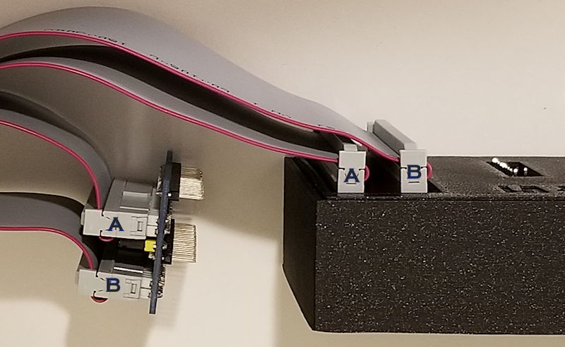
I've got my boards assembled and the cable made, so now it's time to download the code!

Edit:

Botheration... I think the only keys on my screen/key assembly that are working are right and reset. Bugger all happens when I press left, select or down.

:-(

yorkshire_spam2019-06-16 12:52:47
 

yorkshire_spam

Active member
vacBacker
Credits
763CR
Fixed it by tweaking some settings in the Arduino software.
Is there a moron's guide to setting the jumpers for each CPU anywhere?

Cheers, Sam
 

Arcadenut

User
Credits
314CR
ok, I need to verify that I have my cables attached correctly.

Can someone please take a look at let me know if I'm good to go?

Thanks!

Ardunio_Tester_Cables_Attached_1_Small.jpg


Arcadenut2019-06-23 06:12:09
 

Judder

Active member
Feedback
2 (100%)
Credits
976CR
Arcadenut said:
ok, I need to verify that I have my cables attached correctly.

I think that's correct from a quick look at the picture

Have a look at these pictures to check

http://www.ukvac.com/forum/arduino-incircuit-tester-build-project_topic349525_post934580.html#934580

http://www.ukvac.com/forum/arduino-incircuit-tester-build-project_topic349525_post934622.html#934622

and I nearly forgot that I labelled all the pins and everything else in this post too :)

http://www.ukvac.com/forum/arduino-incircuit-tester-build-project_topic349525_post935957.html#935957

Judder2019-06-23 17:48:29
 

yorkshire_spam

Active member
vacBacker
Credits
763CR
Thanks, I'd spotted the table on the website, I guess what I should have said was, I've figured out the ground jumpers on the CPU head board, but what are J13 and J14 for and how do they work?

I suppose 10 minutes with a continuity tester or the board layout and I can figure it out... I'm just lazy! (computer programmer lazy)

Cheers,

Sam

Arcadenut said:
yorkshire_spam said:
Fixed it by tweaking some settings in the Arduino software.
Is there a moron's guide to setting the jumpers for each CPU anywhere?

Cheers, Sam

From this page:

http://www.zzzaccaria.com/arcade/ArduinoMegaICT.htm

jumper_table.png
 

Arcadenut

User
Credits
314CR
Judder said:
Arcadenut said:
ok, I need to verify that I have my cables attached correctly.

I think that's correct from a quick look at the picture

Have a look at these pictures to check

http://www.ukvac.com/forum/arduino-incircuit-tester-build-project_topic349525_post934622.html#934622

Thanks. That picture has the cables opposite from mine, but should be equivalent. I made the assumption that Pin 1 was the upper left from where you can read the connector label.

Those multi colored cables make it a real PITA to figure out what goes where
smiley17.gif


Guess we'll find out if it works later today... crossing fingers!
 

wondras

Newbie
Credits
89CR
yorkshire_spam said:
Oooh cool! Buttons are working now thanks to Lurch.
Ill grab the repo with the BZ support, build and hook up to the PCB!

I think you're the first person to try the BZ support, though it's working well for me. There's an experimental POKEY test in the 'pokey' branch you might want to try as well.

If anything doesn't seem to work as advertised, please let me know!
 

yorkshire_spam

Active member
vacBacker
Credits
763CR
wondras said:
yorkshire_spam said:
Oooh cool! Buttons are working now thanks to Lurch.
Ill grab the repo with the BZ support, build and hook up to the PCB!

I think you're the first person to try the BZ support, though it's working well for me. There's an experimental POKEY test in the 'pokey' branch you might want to try as well.

If anything doesn't seem to work as advertised, please let me know!

Cool, I'll take a look. I got the fluke to perform a series of tones on the pokey on a Centipede board years ago. Maybe we could write a generic pokey test where the "game" data sets the pokey base address or something?
 

wondras

Newbie
Credits
89CR
yorkshire_spam said:
I got the fluke to perform a series of tones on the pokey on a Centipede board years ago. Maybe we could write a generic pokey test where the "game" data sets the pokey base address or something?

Cool! I wish I had a Fluke, though the Arduino ICT has the potential to cover a lot of ground.

Yup, the POKEY test class is in a separate file, and you pass the base address to the constructor. It generates a tone in each of the four channels, reads switches on the pot inputs, and reads values from the random number generator. I implemented it for both Battlezone and Asteroids Deluxe.

The reason it is "experimental" is that it adds a doClocks() method to CFastPin, which creates a sufficiently fast series of clock pulses to allow the POKEY to produce audio. I'm not sure how everyone will feel about this.

I'm also attempting to create tests for the BZ mathbox and vector generator, but so far they are pretty unreliable. I think it's because the phi2 clocks created by the ICT are slow and asynchronous, so I can't send a single go/write strobe. Still noodling on how to accomplish this...
 
Top